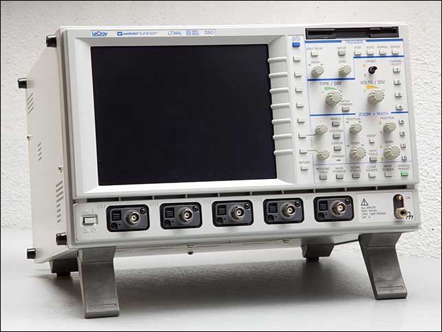
I managed to get a cheap “for parts” oscilloscope that arrived with a dark screen, damaged CH1 BNC connector and broken ground terminal. One knob was missing and the floppy drive did not work. The encoders where hard to use, very erratic. You turned them fast and nothing moved and you turned them slowly and the value jumped to infinity. Very dirty outside, and incredibly dirty inside.
I badly wanted this four-channel oscilloscope mainly because you can choose the color of the traces (something that can’t be done on most modern scopes). I had to hack my modern scope so I could tell one trace (yellow) from the other (green). Well, anyhow, this is what I did to put this scope back in service again.

The floppy drive
The floppy drive simply suffered from a stretched belt, so it was just a matter of getting the right replacement. Someone in eBay was selling a genuine replacement for the drive and I was lucky to get it. Simple as being at the right place at the right time…
The LCD backlight
This one I knew was going to be easy. The Sharp LQ084V1DG21 is found in many instruments of the era and it is well known for developing backlight problems. The CCFL tube ages and, even before that happens, the reflective thin paper that surrounds the tube can turn black and warped, preventing the light from reaching the difuser, which darkens the screen. I have a dedicated article on converting to LED backlight the Sharp LCD module. You might want to take a look at that.
The original driver has a ENABLE pin that keeps the LCD dark until the CPU actually initializes it, to prevent the screen from appearing completely white during a few seconds on power-up. I haven’t worried about this in the past but this time I wanted to take care of it. I measured the delay from power-on to the backlight enable signal. I measured the delay (note that upgrading the firmware to the latest one that displays “WaveRunner” at boot reduces the boot time and the delay… yes I had to reprogram the PIC grrrrr) from power-on until it went low:
Can you see the color difference between the two traces? I can’t, and that is why I had to hack that scope.

Agilent DSO-X oscilloscope colorblind hack (click on picture to follow)
I built a small PCB with the regulator, a 2n7000 to cut the current and a tiny PIC microcontroller for the delay so I could about routing the enable signal to my circuit (oh, and because I love little PICs):

I re-used the original connectors. You can see the PIC wired to the PicKit2 programmer here:

The PCB fits on the position of the original driver, you only need to wire it to 12V (I wired the LED strips in series this time) and the ENABLE signal:

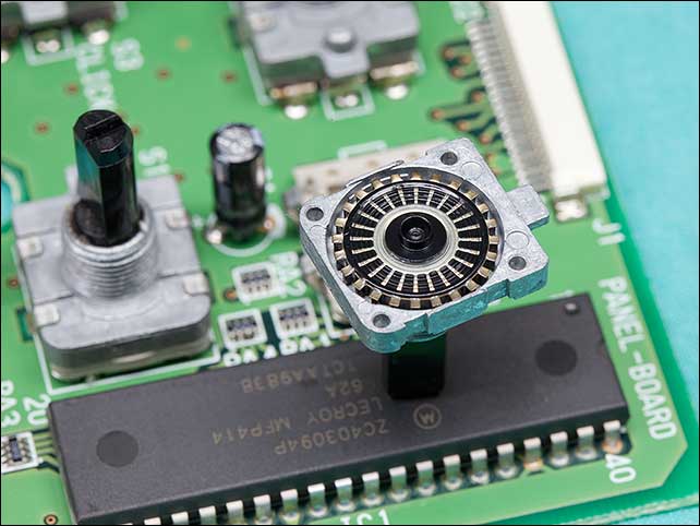
The encoders
There is great information about this scopes in the LeCroyOwnersGroup@groups.io forum, including a nice guide with part numbers for the encoders. I suspected they actually did not replacement, but just a bit of maintenance. And I was right. Once cleaned they work perfectly fine. They might not last like this as long as new ones but I won’t probably get to that point anyway. By the way, the complete service manual, including schematics is available freely on the web, it’s easy to find.
The good news for you if you are trying to clean the encoders is that you don’t need to remove them from the PCB because they are opened from the shaft’s side. You do need to desolder a two-row pin header to remove the PCB that covers them though:

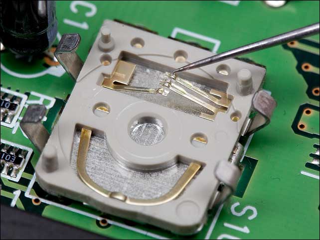
Once you gain access to the top side of the encoders, use a flat screwdriver to free from the tabs the part that holds the shaft.


I found the track to be actually clean, the problem was a deposit on the surface of the wipers, right where they slide on the surface of the contacts. It may look big on the picture, but you will need a steady hand and a decent microscope/lens if you don’t want to smash them. Carefully remove the deposit with a sharp tip:

After cleaning the wipers, I carefully forced them into a higher position so they have a bit more pressure on the contacts. This is a good moment to move a bit of the grease that you’ll find over the length of the wiper to the tip that you previously cleaned:
The BNC connector
As explained by the seller, the CH1 BNC connector had suffered a big impact and it was damaged to the point that it was impossible to insert a male BNC connector into it. I knew it was going to be hard to find a replacement, so I replaced it with the one from the EXT trigger port, which was not as important for me. After a long unsuccessful search for that strange Hirose connector, I found that Lecroy used the same connectors in oscilloscope adaptors of that era so I bought a cheap one:


I cleaned the pads for the EXT trigger BNC connector and soldered the replacement one there:


The ground post had suffered a crash and was out of aligment so I removed it and flattened the metal plate:


The FAN
The fan was noisy and old so I replaced it with a very silent Noctua PC fan that provides more than enough airflow:

The missing knob
I could make a similar one with the 3D printer, but I still hope to find a genuine replacement for this now as-new looking oscilloscope that it is still a workhorse:
A colorblind’s dream
This is why I like this scope. Four channels with the colors you want, with the colors you can actually see:
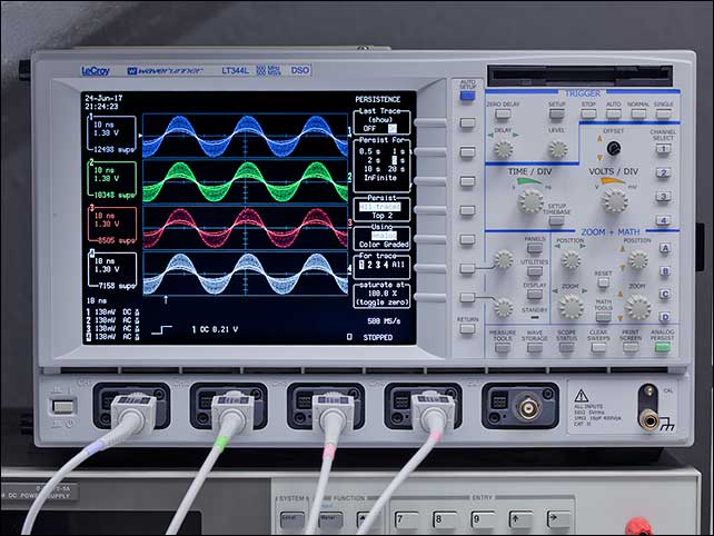
I managed to get one knob so now the scope is complete !