We wanted to be able to remotely monitor the operating conditions of the EA4YAF repeater and also provide CW ID. The idea was to transmit a short 1200bps packet with the telemetry information, just after the CW ID, every 10 minutes. This is how the system was designed an built.

CW ID
CW is generated with a single pin of the PIC creating a square wave. The algorithm used was the same as used in the NCDXF beacons, original idea from Curtins K6KU.
“…The program for sending Morse code, written by Jack Curtis, K6KU, was carried over from the original beacon. The messages to be sent by the beacon are stored in the memory as a string of ASCII characters, rather than as a string of dots and dashes. To send a character, the character is looked up in a table that specifies the dot and dash representation of the character. As one might imagine, a 1 bit in the specification stands for a dot and a 0 bit stands for a dash; the tricky part is to find some simple way to specify how many dots and dashes a particular character requires. The solution is useful for any program that sends Morse code. The unused bit positions are filled with a 1 followed by enough 0s to fill the byte: A is encoded as 1010000 for dot-dash; B is encoded as 01111000 for dash-dot-dot-dot; and so on. If you have written any bit-twiddling programs, you can probably imagine the algorithm for sending the character specified in such a way: If the high-order bit of the specification is a 1, send a dot, otherwise send a dash. Shift the specification left one bit position, throwing away the old high-order bit and filling the low-order bit with a 0. If the specification is now 10000000, exit; otherwise, go back to send the next dot or dash…”
Pressure Sensor
Ambient pressure is measured with an automotive sensor. It was removed from it’s heavy-duty casing and it provides a 0-5V signal depending on pressure. EA4BCR plotted a Vout vs pressure graph and it was clearly seen that pressure is directly related to voltage. A simple resistor and 100nF capacitor was all needed to feed the signal to one of the PIC’s ADC channels. Excel was used to get the best-fitting curve, with no altitude compensation. Linear factor was so close to 1 that I decided to simplify it and asume it was actually one. Altitude compensation was made onsite after recompiling the program with the correct parameters.

Charge Current Sensor
This was probably the most important feature and also one of the most difficult. After some tests I decided to use a high side ZTX1012 sensor, located between the charge controller and the battery, connected to one of the PIC’s ADC channels. With the sensing resistor used (see picture), it provides a maximum reading of 13A with 13mA resolution if using the PIC’s Vdd as reference for the ADC.

Anemometer
EA4BCR had a nice Carlo Gavazzi PV-01-2 anemometer, which provides ten pulses per revolution. The PIC powers the anemometer only while measuring wind speed to reduce battery drain. This is done simply by wiring the anemometer ground to the collector of a 2N3904 transistor with the emitter to ground and base to a PIC output with a 1K resistor. Measurement is done counting the number of pulses that take place during a 800mS period, which gives enough resolution and range with the 8-bit timer: 240 counts at 30m/s wind speed and 16 pulses at 2m/s which is the lowest valid speed reading for this anemometer.
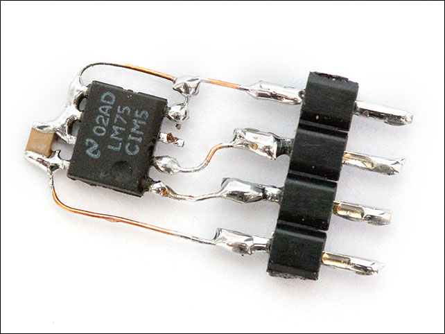
Temperature Sensor
Temperature is measured remotely with a common LM75. LSB is discarded so an 8 bit integer is enough to store temperature. The LM75 is suspended on thin wires, which is simple & dirty, and also minimizes thermal mass…
TinyPack Integration
AX25 generation is done with a TinyPack. The PIC send a serial stream with the telemtry data right after generating the CW identification. The PIC’s PTT pin drives a 2N3904 that has the collector wired to the NPN transistor used by the TinyPack PTT circuit. The PIC holds the PTT a bit until the TinyPack responds to the serial command and activates the PTT by himself. Audio is fed to the variable resistor for modulation adjustment in the TinyPack, which means this setting also afects CW audio.
The Hardware
Everything except remote temperature sensor, anemomenter and charge current sensor is built in a metal enclosure using a project PCB as seen in the first picture. The schematic of the system is the following, you can right-click and save as to get a bigger image.

The Firmware
The firmware was written in PICC and it is commented, take a look at it here.